Definition of Resistor
Resistor
• High Frequency Effects
Voltage Coefficient of Resistance
Noise of a Resistor
• Power Rating
• Voltage Rating
Types of Resistor
• Carbon Composition
• Resistor Color Code
• Wire Wound
• Metal Film and Carbon Film
Definition of Resistor
A resistor offers resistance to the flow of current . The resistance is the measure of opposition to the flow of current in a resistor. More resistance means more opposition to current . The unit of resistance is ohm and it is represented as Ω. When one volt potential difference is applied across a resistor and for that one ampere of current flows through it, the resistance of the resistor is said to be one Ω. Resistor is one of the most essential passive elements in electrical and electronics engineering.Resistor
It is some time required to introduce electrical resistance in different circuit to limit the current through it. Resistor is an element of circuit which does the same. Such as series connected resistor limits the current flowing through the light emitting diode (LED). In addition to that resistors serve many other purposes in electrical and electronic applications.
The most essential requirement of a resistor is that its value of electrical resistance should not vary with temperature for a wide range. That means resistance variation with temperature must be as minimal as possible for a wide range of temperature. In other word the temperature coefficient of resistance of must be minimum for the materials by which a resistor is made of.
High Frequency Effects on Resistor
The effective resistance value of a resistor may be changed when it is subjected to alternating voltage. Not only that the value of resistance varies with variation of frequency of supply voltage. This change of resistance with frequency is called Boella effect. Actually it is not practically possible to make an ideal resistor. Practically it may have some inductor and capacitance in addition to its resistance. Therefore, the value of impedance of the resistor may vary with frequency. That is why a resistor is referred to be used within its useful frequency range. Useful frequency range is defined as the highest frequency limit beyond which the impedance of the resistor crosses its tolerance value.
High frequency effect on resistor depends upon its constructional feature. The impedance of wire-wound resistor increases with frequency. On the other hand composition resistor reduces its impedance with increasing frequency. The impedance of film resistors does not change up to 100 MHz and then it decreases. Film resistors have the most stable high-frequency performance.
The high frequency response of a resistor may also depend up to some extend on diameter of the resistor. It is seen that smaller diameter resistor has better frequency response. Because of that the length – diameter ration of high-frequency resistors is between 4:1 to 10:1.
Voltage Coefficient of Resistance
The resistance of a resistor may also vary sometime with applied voltage across it. This change is expressed as a percentage of the resistance at 10% of rated voltage. Thus the voltage coefficient of resistance is give by
Where R1 is the resistance at the rated voltage V1 and R2 is the resistance at 10% of rated voltage V2.
Noise of a Resistor
Noise in a resistor is caused by its applied voltage, its physical dimensions, and materials by which it is made of. The noise includes Johnson noise, noise due to flow of current, noise due to cracked bodies, and noise due to loosen end caps and leads of the resistor. For variable resistors the noise can also be caused by the jumping of a moving contact over turns and by an imperfect electrical path between the contact and resistance element.
Johnson noise is thermal noise. This noise depends upon temperature but does not depend upon frequencies. As this noise is same for all frequencies it is referred as “white noise”. The magnitude of thermal noise is given by,

Where, ERMS is the value of the noise voltage (V) in rms, R is the resistance measured in ohm, k is Boltzmann constant (1.38 X 10 – 23 J/K), T is the temperature measured in Kelvin, and Δf is the bandwidth in Hz over which the noise energy is measured.
Power Rating of Resistor
When current passes through a resistor there would be I2R loss and hence as per Joules law of heating there must be temperature rise in the resistor. A resistor must be operated within a temperature limit so that there should not be any permanent damage due high temperature. The power rating of resistor is defined as the maximum power that a resistor can dissipate in form of heat to maintain the temperature within maximum allowable limit. How much power a resistor will dissipate depends upon material, dimensions, voltage rating, maximum temperature limit of the resistor and ambient temperature.Voltage Rating of Resistor
This rating is defined as the maximum voltage that can be applied across a resistor due to which power dissipation will be within its allowable limit. Actually voltage rating of resistor is related to the power rating. As we know that power rating of resistor is expressed as
Where V is the applied voltage across the resistor and R is the resistance value of the resistor in ohms.
From above equation it is clear that for limiting P, V must be limited for a particular resistor of resistance R. This V is voltage rating of resistor of power rating P watts and resistance R Ω.
Types of Resistor
There are different types of resistor depending upon their construction, power dissipation capacities and tolerance of the value. Such as- Carbon Composition Resistor
- Metal Film Resistor
- Carbon Film Resistor
- Non Linear Resistor
- Varistor
- Thermistor
Carbon Composition Resistor
These types of resistor are very commonly used low cost resistor. The construction of carbon composition resistor is very simple. It is also commonly referred as carbon resistor. It is mainly made of carbon clay composition covered with a plastic case. The lead of the resistor is made of tinned copper. The main advantages of these resistors are that they are easily available in local market in very low cost and they are very durable too. But the main disadvantage is that they are very much temperature sensitive. These resistors are available in wide range of values. It is available in as low as 1 Ω value and it is also available in as high as 22 Mega Ω value. The tolerance range in resistance of carbon composition resistor is of ± 5 to ± 20 %. Such resistor has a tendency of electric noise due to passage of electrical current from one carbon particle to other. Where low cost is the main criteria of designing a circuit rather than it's performance, these resistors are normally used.
These carbon resistors are provided with different colored band on their cylindrical body. These color bands are code for the resistance values of carbon composition resistor along with their tolerance range.
Resistor Color Code
There are mainly four color bands provided on the body of resistors and each color indicates unique digit. Such as Black ⇒ 0, Brown ⇒ 1, Red ⇒ 2, Orange ⇒ 3, Yellow ⇒ 4, Green ⇒ 5, Blue ⇒ 6, Violet ⇒ 7 Gray ⇒ 8, White ⇒ 9. The first and second color bands indicate a two digits number. The 3rd color band indicates the power of ten as multiplier. The fourth band indicates the tolerance.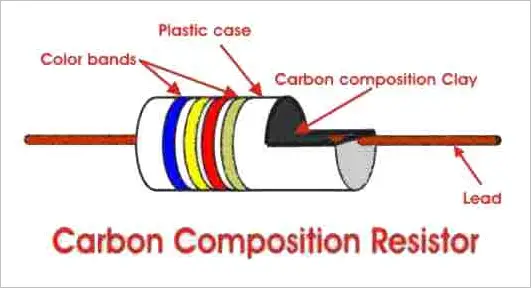 If fourth band is of golden color the resistors may have ± 5 % tolerance in its value, if fourth band is of silver color, the resistor must have ± 10 % tolerance and if there is no fourth band provided, then the carbon resistor may have ± 20 % tolerance in it's value.
Suppose we have a carbon composition resistor which has four color bands among which first band is blue second band is yellow, third band is red and fourth band is golden. So from the above rule the first digit of the number will be 6 ( as Blue ⇒ 6 ), the second digit of the number will be 4 ( as Yellow ⇒ 4 ) and the multiplier of this two digit number will be 102 ( as Red ⇒ 2 ). Hence electrical resistance value of the resistor will be 64 X 102 Ω. The tolerance of that value may be ± 5 % as the color of fourth band is golden.
Video Presentation-Resistor Color Codes
Wire Wound Resistor
The construction of this type of resistor is also very simple. In wire wound resistor a wire of manganin or constantan is wound around a cylinder of insulated material. The temperature coefficient of resistance of these two materials is almost zero. So there would no resistance variation with temperature. The wounded wire is covered with an insulating material such as baked enamel. This cover of insulating heat resistible material is provided to resist the effect of ambient temperature variation. Different sizes and ratings of wire wound resistor can easily be achieved by using different lengths and diameters of the wire. These resistors are easily available for wide range of ratings. The range of resistance values varies from 1 Ω to 1 MΩ. Typical tolerance limit of these resistors varies from 0.01 % to 1 %. They can be used for high power applications of 5 to 200 W dissipation ratings. The cost of these resistors is much higher than carbon resistor. Normally wire wound resistor is used where carbon composition resistor cannot meet the purpose because of its limitations.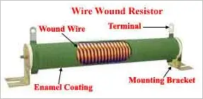
The main disadvantage of this resistor is the inductor that arises because of its coil like structure. At high frequency the behavior of the circuit may be changed due to its reaction. This problem can be solved if one half of the wire is wound in one direction and other half in opposite direction so that the inductor due to these two halves cancel each other hence net inductive effect of the resistor becomes nil. The non - inductive wire wound resistor is ideal for high frequency circuit but it is costlier than an ordinary one.
Metal Film Resistor and Carbon Film Resistor
Basic structure of this type of resistor is constructed by means of film deposition technique of deposition a thick film of resistible material such as pure carbon or metal on to an insulating core. The desired value of resistance of metal film resistor or carbon film resistor can easily be obtained by either trimming the layer of thickness or by cutting helical grooves of suitable pitch along its length. That means for different resistance values, the length and depth of the helical grooves is maintained accordingly. Metallic contact cap is fitted at both ends of the resistor. The caps must be in contact with resistible film or helical grooves. The lead wires are welded to these end caps. Metal Film Resistor or Carbon Film Resistor can be made up to a value of 10,000 MΩ and size of this type of resistor is much smaller than wire wound resistor resistor. Because of their constructional features these resistor are fully non - inductive. The accuracy level of metal film resistor can be of order ± 1 % and they are suitable for high grade applications.
Carbon film resistor givers lower tolerances and smaller values of electrical resistance than those available with metal film. However the carbon film posses a mildly negative temperature coefficient of resistance which is very useful for certain electronic circuit.
No comments:
Post a Comment